A test circuit on breadboard for my Autothrottles (moving throttle levers for my flight simulator) project.
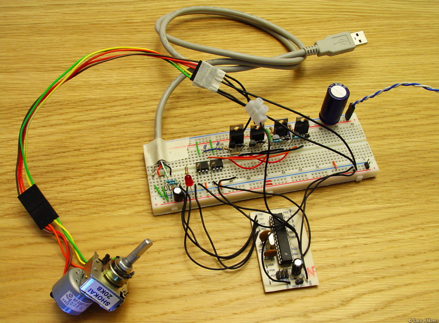 Full system
The complete prototype setup: The digital part of the circuit is powered and controlled from the USB bus. The AVR microcontroller interprets the USB commands and enables the necessary output signals. Additionally, the AVR contains the A/D converter to read the the potentiometer value.
Exposure Time: 0.8 sec • F-Number: f/8.0 • ISO Speed Rating: 100 • Focal Length: 9.70 mm
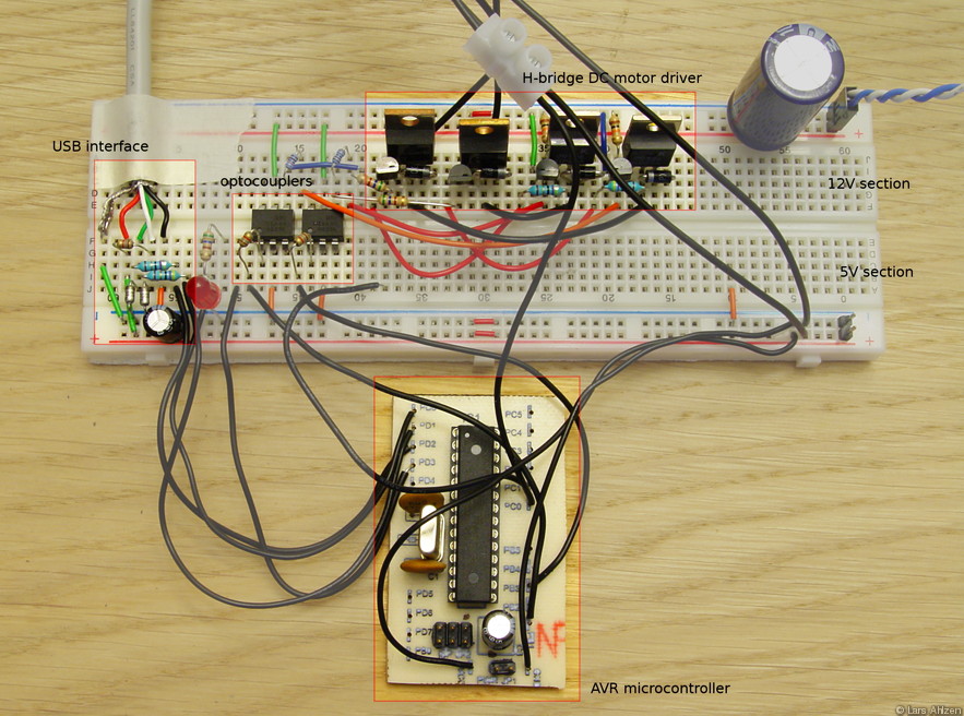 Protoboard
Since the DC motor is powered by +12V from a separate power supply, and the rest of the circuit is powered from USB, the prototype board is divided into two separate sections, 5V and 12V. To play safe, the two sections are completely isolated by optocouplers. The DC motor controller is a basic H-bridge with TIP29A and TIP32C power transistors as drivers (similar to this design, but modified to use components I had at home). The additional three wires to the motor/pot assembly are for the potentiometer value, ground and voltage reference. These are connected to the A/D converter of the AVR. The USB, finally, uses the USBtiny software implementation of the USB protocol.
Exposure Time: 1 sec • F-Number: f/8.0 • ISO Speed Rating: 100 • Focal Length: 12.30 mm
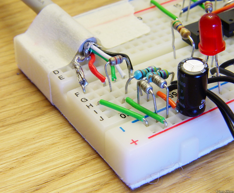 USB interface
Exposure Time: 1 sec • F-Number: f/8.0 • ISO Speed Rating: 100 • Focal Length: 17.90 mm
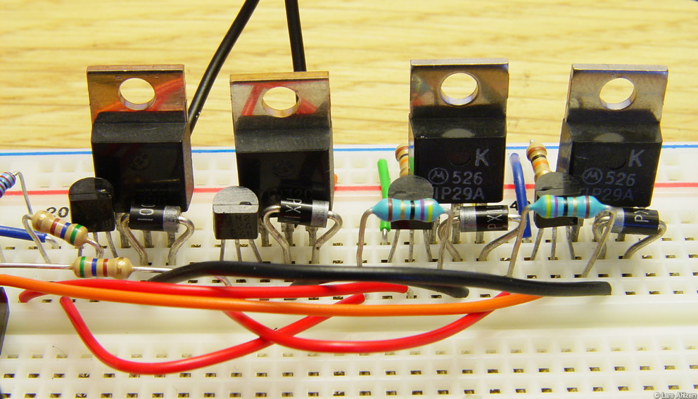 DC motor driver
Exposure Time: 1.6 sec • F-Number: f/8.0 • ISO Speed Rating: 100 • Focal Length: 16.40 mm
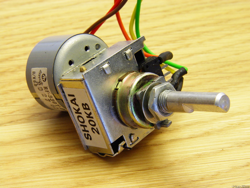 Motorized pot
These motorized pots are extremely cool! They contain a 20kΩ potentiometer, connected to a DC motor via a gear assembly and clutch (for manual turning). While I assume that these were originally intended for applications such as a motorized volume control on a stereo, they're just perfect for this project. And if this wasn't enough, they were very cheap at the Electronic Goldmine.
Exposure Time: 1.6 sec • F-Number: f/8.0 • ISO Speed Rating: 100 • Focal Length: 16.40 mm


